


Toyota Avensis — System Too Lean
By Dave Hill
www.londonroadgarage.com
Quite a simple one this, but I thought it was interesting.
A 2002 Toyota Avensis came in with the MIL on and two DTCs present: P0171 and P0174 System Too Lean on banks 1 and 2 respectively. On the first visit I was asked to clear the codes (it was a motor trader’s car!) which I did, with the suggestion that it would most likely return.
Sure enough a couple of days later the car is back for a proper look. Fuel trims suggested an issue…
- Short FT 1 = -18.0%
- Long FT 1 = 0.7%
- Short FT 2 = -19.6%
- Long FT 2 = 1.5%
So out with the PicoScope lab scope and time to look at some relationships between both upstream oxygen sensors and the mass airflow meter. These are 1 volt zirconia types and there are 4 in total. Two upstream and two downstream. The MAF is a Denso type.
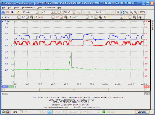
Here is an overview look at both O2 sensors and MAF. The O2 sensors can be seen to switch nicely at the start of the capture, but as we zoom in, it can be seen that there is a problem when the throttle is “snapped open”.
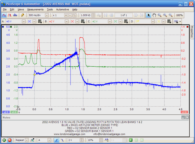
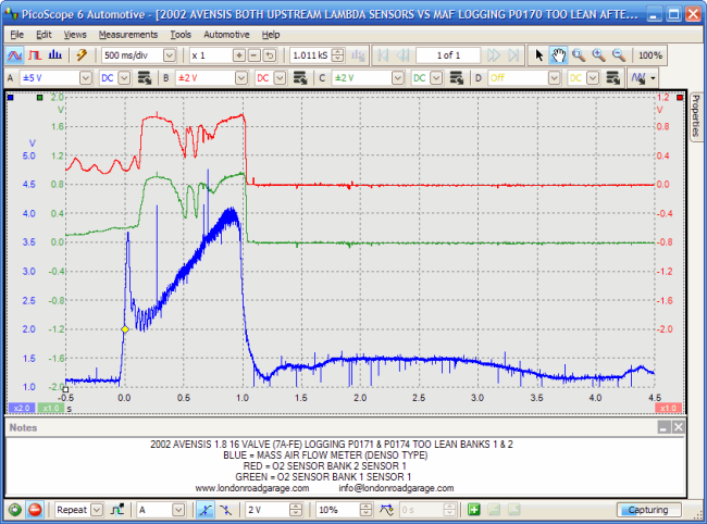
Next is the more conventional capture that I make regularly. It is pretty clear here that the MAF sensor is performing badly, not just in the fact that the peak voltage is less than 3500 mV but also the “gulp” section of the capture is very weak too. Notice how both O2 sensors remain lean throughout the wide open throttle phase.
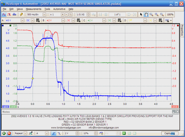
Not having seen many of this type of MAF, I am a little cautious about just fitting one without a bit more diagnosis. Other factors can lead to weak MAF sensor output and it is important to rule as many things out as possible. I use a sensor simulator often to help prove a point. This time I am pushing a more expected 4.5 volts down the MAF signal wire at the same time as an assistant performs a “snapped” throttle test.
The boost given to the MAF signal has given the desired response from the oxygen sensors and I feel a little happier about replacing the MAF. I then took an unusual step and decided to have a look at the MAF to see if it was dirty. I was surprised to see the two elements were very dark and dusty. A quick spray of carb cleaner rejuvenated it to a nice shiny state.
Once refitted, the same captures as taken previously were taken again to confirm a fix. Here is the same overview-style capture as before, but now the O2 sensors can be seen to go rich throughout the snap test and they also start to recover quicker afterwards and start to switch again.
Again the classic capture. Showing a good “gulp” and a much healthier peak voltage. The engine revved much more responsively too!
An emissions test proved successful and here are the fuel trim figures now…
- Short FT 1 = 0.0%
- Long FT 1 = -3.2%
- Short FT 2 = 0.0%
- Long FT 2 = -3.9%
Sorted!
A simple problem by today’s standards, but I feel it is made even clearer with the use of a scope.
Cheers all.