|
 |
|
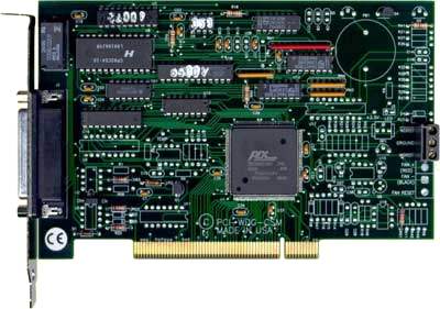
Watchdog Timer Card
Features
- Universal PCI, PCI-X, 3.3V and 5V compatible (Call for PCI-Express availability)
- Watchdog timer to detect computer malfunction
- Optional computer power supply monitor
- Optional internal computer temperature monitor
- Optional measurement of computer internal temperature
- Optional fan-failure detection, watchdog time-out buzzer, and opto-isolated reset output
- RoHS Available. Please contact us for ordering information
This multifunction card contains a watchdog timer. Additionally, one or more options may be included on your card. These are: a computer power supply monitor, a computer internal temperature monitor, an optional capability to read the temperature, a fan-speed monitor, and an on-card buzzer to signal watchdog timeout. PCI-WDG-CSM continuously monitors critical PC functions. When a fault occurs, the card automatically generates outputs that can be used either to initiate corrective action or to generate alarms.
WATCHDOG
It's a fact of life that computers and programs can fail. If a computer or program fails it can cause catastrophic damage. Even if a program merely locks up, an unattended computer could be down for days. There are two methods to reduce risk of computer or software failure; (a) redundancy and (b) a watchdog circuit. Neither method offers 100% assurance, but both of these methods reduce risk or consequences of failure. Redundancy, a duplication of computer circuitry, is very expensive. On the other hand, ACCES' Watchdog card offers excellent protection from temporary malfunctions at very low cost.
Your application program must communicate with the watchdog circuit at prescribed intervals. If this communication ("prompt") is missed, the Watchdog can be programmed to initiate a computer reset (reboot). If the reboot is successful, operation, may be returned to the previous application program. If the failure was temporary, proper operation is resumed. If, however, the failure is persistent, the Watchdog will continuously reset the computer. The more frequently the Watchdog is prompted (and shorter Watchdog time selected), the less time a faulty computer has to cause damage.
The method used by the WDG-CSM card to detect loss of computer function is as follows:
- A type 82C54 counter/timer is used. This chip contains three 16-bit counters. A number greater than zero is set into the chip's Counters 0 and 1 by your application program. The Watchdog is armed by software command and both counters begin counting down. As long as the computer is operating properly, both counters will be periodically reloaded to their original programmed values by your application program before both counters have counted down to zero.
- If your software fails to reload the counters, then both counters continue counting until zero is reached (timeout). When the counters 0 and 1 reach zero, either the power-good line is held low for approximately 16 milliseconds (performing a hardware reset) through a relay contact, or external lines (either relay contacts or a de-bounced opto-isolated switch) are active while a buzzer sounds (if enabled). When a reset condition occurs, the reset circuit is active until a reset pulse returns from the system bus or power is cycled to the system.
The clock frequency to Counter 0 is derived from the computer's color clock and is 2.0833 MHz. (The period is 1.117 µsec.) The output of Counter 0 is used as a clock to Counter 1. Since each counter can divide by any whole number from 2 to 65,536 (216), the watchdog timeout period may vary from about 10 microseconds to 4800 seconds.
The Watchdog card can generate an interrupt request one Counter 0 period-width before the reset timeout. For example, if a reset period of 60 seconds is used with a 5 milli-second delay stored in Counter 0 (the result of a maximum value delay), an interrupt would occur at 59.995 seconds. This gives the Interrupt handler software 5 milliseconds to refresh the watchdog before a reset action occurs. This should allow your software to take corrective actions if the system software continued to run but the software that should have reset the watchdog had failed. Also, this timeout-imminent warning can also be used to initiate an orderly shutdown of Windows programs.
The interrupt request (IRQ) output is tri-stated at a high-impedance when it is not sending an interrupt request (1 µsec). Thus, that IRQ number can be shared with other I/O cards that have shareable ability. IRQ's 2 through 7, 10, 11, 12, 14, and 15 are available.
There are several outputs from the watchdog circuit:
- Double-pole double-throw, Form C, relay contacts on the rear panel I/O connector
- An opto-isolated reset output on the rear panel I/O connector
- An opto-isolated complement of the reset output on the rear panel I/O connector
- A buffered TTL CTRGATE (counter enabled) output on the rear panel I/O connector
- TTL reset signal on internal terminal block TB1
- The complement of that output at terminal 3 of TB1
- A Watchdog 56KHz heartbeat on the rear panel I/O connector
- Un-fused 5V DC output
As noted in items b. and c. above, opto-coupler outputs (one ON when the other is OFF) are provided for use where relay contact bounce could be a problem. Further, as noted in e. above, a buffered discrete output is also provided. This output goes high to signal a watchdog reset condition.
Finally, a 56 KHz, TTL-level, 50% duty cycle signal is provided at I/O connector pin 13 when the watchdog circuit is enabled and no reset is in progress. Otherwise, this output is in a low state.
OPTIONS
You may order one or more options installed as mentioned in the opening paragraph of this description. The following paragraphs describe these options.
- Computer Power Monitor: Three computer power supplies ( 5V, 12V, and -12V) are monitored. If one or more of those voltages are more than 6% outside of their nominal values, then two bits of a Status Register indicate whether there is an overvoltage or an undervoltage. In addition, an interrupt request can be generated.
- Computer Temperature Monitor: If this option is installed, Option 01 must also be installed. This option monitors ambient temperature inside the computer chassis. The temperature monitor circuit compares the output of an LM334 temperature sensor with a preset DC voltage level. The output of the comparator circuit can be read at a bit location of the Status Register and, also, can cause an interrupt request if that temperature exceeds the factory preset limit (50oC).
- Computer Temperature Measurement: This option requires presence of both Option 01 and 02. When this option is included, an onboard 8 bit A/D converter provides means for a software read of the measured temperature. Resolution is to approx. 0.7oF.
- This option provides three functions as follows:
- Change of State: Differential digital inputs are accepted through pins 17 & 18 (ISOIN0) and pins 19 & 20 (ISOIN1), are opto-isolated and reported in the Status Register. The change-of-state also generates an IRQ interrupt request.
- Buzzer: The buzzer is under software control and can be turned on by programming a "write" to Base Address 4 or off by programming a "write" to Base Address 5 if Counter #2 is configured in mode 1. Configuring Counter #2 in mode 0 will defeat the buzzer entirely.
- Opto-Isolated Outputs This option provides an opto-isolated reset signal at pins 4 and 5 (Isolated Reset Output) of the DB25F connector. An opto-isolated inverse of the reset signal is also provided across pins 6 and 7 (Isolated NOT Reset Output) of the same connector.
- This option replaces the opto-isolated reset output capability of Option 04 with capability for two isolated digital outputs under computer control. Option 04 must be installed.
- Fan Speed: This function is usable only in computers which use fans that have a tachometer output. If fan speed falls to unsafe levels (i.e., if the tachometer output falls to less than 50pps), an interrupt request is generated. (Both Options 01 and 02 must be installed)

Specifications
Watchdog Timer
- Time-out: Software selectable from 4 µSec to 2060 seconds.
- Output Pulse Width: 16 mSec minimum.
- Clock: 2.08333 MHz, derived from computer clock (33 MHz÷16).
- Address: Continuously mappable within 000 to FFFF hex I/O range.
- Relay Output: DPDT, Form C, max. switching current 2A DC at 30W or 1.25A AC at 30VA max.
- Interrupt Output: PCI-INTA.
Status Monitor Options
- Option 1: IRQ and status register indication if 5, 12, or -12 V exceed /- 6% of nominal.
- Option 2: Temp. Alarm IRQ and status register indication at 122o F and above.
- Option 3: Temp. Measurement from A/D converter, LSB = 0.7o F (factory adjustable).
- Option 4: Fan Speed: IRQ and status register indication whenever fan's tachometer output drops below 50pps (custom factory settings available).
- Buzzer: Audio Alert signals watchdog timeout. Can be disabled by software.
- LED Output: 5VDC, through 470 ohm resistor
- Isolated Outputs: Complementary opto-isolated reset outputs (2).
- Isolated Inputs: Two, opto-isolated, 5 mA typical load. Can be read at base address 4. These bits generate Change-of-State IRQs.
- Option 5: Replaces opto-isolated Reset outputs with computer generated digital outputs. The Buzzer does not function when this option is installed.
- Option 6: Pulse-width modulates power to the fan to control fan speed. Speeds fan up when excessive internal computer temperature is sensed.
Environmental
- Operating Temperature Range: 0o to 60o C.
- Storage Temperature Range: -50o to 120o C.
- Humidity: 10% to 90% RH, non-condensing.
- Power Required: 5 VDC at 125 mA with no options, 250 mA with all options installed.
- Size: 6.7" (170 mm) long x 3.9" (99 mm) high.
Regulatory Compliance
- This product is in full compliance with CE requirements.
 When ordering RoHS products, please identify this need by using a unique model number suffix, "-RoHS" on all orders. For pricing and lead times, please contact your sales representative. When ordering RoHS products, please identify this need by using a unique model number suffix, "-RoHS" on all orders. For pricing and lead times, please contact your sales representative.
| Part Number |
Price(USD) |
| PCI-WDG-CSM |
|
| Available, call for special pricing |
|
| Option 01 |
10.00 |
| Option 02 |
10.00 |
| Option 03 |
15.00 |
| Option 04 |
15.00 |
| Option 05 |
20.00 |
| Option 06 |
15.00 |
View / Download Manual (in .pdf format)
Acquisition Control Communications Engineering / Systems
When ordering RoHS products, please identify this need by using a unique model number suffix, "-RoHS" on all orders. For pricing and lead times, please contact your sales representative.
| Part Number |
Price(USD) |
| PCI-WDG-CSM |
175.00 |
| Option 01 |
10.00 |
| Option 02 |
10.00 |
| Option 03 |
15.00 |
| Option 04 |
15.00 |
| Option 05 |
20.00 |
| Option 06 |
15.00 |
View / Download Manual (in .pdf format)
|
|
|
|
|
|