Log In

Celebrating 45 Years

Follow us on Facebook for all the latest news, updates and promotions


Credit Cards Accepted


Aurora Probability in Northern Canada

Auroral forecast from AuroraWatch.ca


North America Aurora Map from
NOAA Space Weather Prediction Center

Aurora Map - NOAA


AD8-16 (ADA-8)

 
acces logo 
   

Eight-Bit 16-Input A/D and Counter/Timer Card

Features

  • 16 Single-ended or 8 differential analog inputs
  • Eight-bit resolution
  • Over 16,000 conversions per second
  • Programmable scan rate and voltage ranges
  • Two 8-bit analog outputs
  • Three programmable counter/timers
  • Eight digital inputs
  • Eight digital outputs
  • 5V output, 1 amp, fused


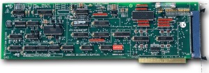
Model AD8-16 (alternate part number ADA-8) is an economical, multiplexed, eight-bit Analog-to-Digital Converter (A/D) and Counter-Timer card for ISA-bus computers. It accepts up to eight differential or 16 single-ended analog inputs (jumper configured). AD8-16 requires a full-size expansion slot. All connections are made through a standard 50-pin connector. Base I/O address selection is via dip switch.

Analog inputs are multiplexed, amplified, held by a sample and hold amplifier, and then digitized by an eight-bit A/D converter. Amplifier gain is selected by software and can differ from channel to channel.

Full scale voltage ranges are ±128 mV, ±5V, 0-255mV, and 0-10V. When operating in the bipolar ranges, the digital output is available in 2's complement or offset binary format. The end-of-conversion signal can be used to interrupt the computer when configured by jumper. You can select from IRQ levels 2-7. The interrupt request is automatically cancelled when the A/D data are read.

There are two 8-bit Digital-to-Analog converters on this card. These D/A's output ranges are -10V to 10V and are intended to drive 10 kilohm or greater load. Maximum output current is 5 mA.

Model AD8-16 also accepts up to eight TTL-level or switch inputs. High inputs may be from 2.5 to 24 VDC or an "open." All digital inputs are pulled up to 5 VDC by 1 kilohm resistors on the card. Low inputs should not exceed 0.8 VDC.

This card also provides eight discrete digital outputs. Each output can sink up to 24 mA with zener diode protection at 5.6 VDC. At system turn-on or reset the digital outputs are tri-stated and remain so until the computer writes to them. For interface to your application program, there are also two highly useful capabilities: Digital Output Read which allows a bit-by-bit readback of the current digital output byte and Command Readback which provides readback of the Control Register.

Model AD8-16 also contains an 8254 timer-counter consisting of three 16-bit counters. These counters may be loaded and read by software. You have complete ability to configure gates, clocks, and outputs either at the I/O connector or via jumpers on the card. A clock at 1/2, 1/4, 1/8 or 1/16 the computer clock rate is available for counter operation. Also, the color oscillator frequency can be used. Alternatively, an external clock may be applied via the I/O connector.

Specifications


Analog Inputs

  • No. of Channels: Eight differential or 16 single-ended inputs.
  • Voltage Ranges: Software selectable, ±128 mV or 0-255 mV w/1 mV resolution, ±5V or 0-10V w/39 mV resolution.
  • Overvoltage Protection: ±40 VDC, single channel.
  • Input Impedance: 10 Megohm
  • Accuracy: ±0.4% ±1 count.
  • Linearity: ±1 count.
  • Resolution: 8 bit binary.
  • Temperature Coefficient: Zero and gain stability each ±1 LSB over full operating temperature range.
  • Throughput: 16,600 conversions/second maximum.

Analog Outputs

  • No. of Channels: 2
  • Output Voltage Range: ±10 VDC.
  • Resolution: 8 bit binary.
  • Output Load: 5 mA maximum.
  • Accuracy: ±0.4% ±1 bit.

Digital Inputs

  • No. of Inputs: 8 TTL- and switch-compatible.
  • Inputs pulled up to 5 VDC by 1 Kilohm resistor.
  • Logic Low: 0 to 0.4 VDC.
  • Logic High: 2.4 to 24 VDC.

Digital Outputs

  • No. of Outputs: 8, TTL/DTL compatible. Outputs are tri-stated at power on and at reset. Zener diode protected at 5.6 VDC.
  • Logic Low: 0 to 0.4 VDC at 24 mA sink current
  • Logic High: 2.5 to 5.0 VDC at 10 mA source current.

Interrupts

  • Level: Jumper selectable, levels 2-7.
  • Enable/Disable: Interrupt generated by completion of A/D conversion. Interrupt cancelled when A/D data are read or when there is a computer write to base address plus 1 (reset interrupt request).

Counter/Timer

  • No. of Counters: Three independent, 16-bit, fully programmable.
  • Clock: Either internal derived from computer clock (or color oscillator frequency) divided by 1/2, 1/4, 1/8, or 1/16 or from external clock source.
  • Drive Capability: 5 LSTTL loads. (2.2 mA at 0.45 VDC).
  • Input Load (Gate and Clock): ±10 mA, TTL/CMOS compatible.
  • Input Clock Frequency:10 MHz max.
  • Active Count Edge:Negative edge.
  • Clock Pulse Width: 50 nSec high / 50 nSec low min.

Power Required

  • 5 VDC at 0.5 A.
    12 VDC at 20 mA.
    -12 VDC at 20 mA.

Environmental

  • Operating Temperature Range: 0° to 60°C.
  • Storage Temperature Range: -40° to 100°C.
  • Humidity: 5% to 90% RH, non-condensing.

Size

  • 13.1 inches (333mm), plugs into a "long slot" in PC

Regulatory Compliance

  • This product is in full compliance with CE requirements.

Part NumberPrice(USD)
AD8-16
View / Download Manual (in .pdf format)
Acquisition Control Communications Engineering / Systems 
 
 
USA Office

Tel:1.877.902.2979-1.425.223.4311
Fax:1.877.329.4324
Address: 1480 Gulf Road, Suite 837,
PO Box 1364
Point Roberts, WA 98281

Western Canada - Vancouver BC

Tel:1.800.663.6001 or 1.604.925.6150
Fax:1.604.925.6170
Address: 2454 Haywood Ave
West Vancouver, BC V7V 1Y1

Eastern Canada - Markham, Ontario

Tel:1.800.465.0164 or 1.905.513.7027
Fax:1.877.329.4324