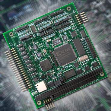
Model 104-DA12-8A is a PC104 board featuring eight independent 12-bit digital-to-analog converters (DACs) and broadly configurable arbitrary waveform generation (ARB) capabilities. Other convenient features include 128K SRAM for waveform data storage, eight 4-20mA current sinks, three 16-bit counter/timers and fused general-purpose 5V and 12V power outputs. An economy version is available without the ARB feature as model 104-DA12-8.
The DACs can be updated individually or simultaneously. An automatic circuit sets the analog outputs to zero at power-on or reset. Each output is buffered by a short-circuit protected op-amp capable of sourcing up to 5mA. Data for updating each DAC may come from either the board's onboard RAM or from the PC/104 bus. The on-board 128 KB (64K sample) RAM and onboard intelligent circuitry provides flexible allocation of between one and eight FIFO buffers/waveforms.
Arbitrary waveform generation capability becomes increasingly necessary as CPUs are burdened with a greater abundance of complex tasks. An arbitrary waveform is a user-defined set of digital values specified point by point over time. These values are then clocked through a DAC to provide the analog output signal. Virtually any waveform can be created using the software tools provided by ACCES and also by third-party software packages. The ARB relieves some of the load placed on the CPU by handling the waveform generation at the hardware level using on-board memory and control logic. This is especially useful in time-critical applications as outputs remain unaffected by latencies inherent in popular operating systems. ACCES I/O’s ARB architecture allows for total flexibility in allocating the onboard RAM across the channels depending on the complexity of the desired waveform. It is even possible to use the ARB for selected channels while operating the remaining channels in the software driven mode.
Counter/Timers
Three 16-bit down-counters, in a type 8254 IC, are included. These are configured as two frequency sources derived from an on-board 2 MHz crystal-controlled oscillator. Counter/Timers 1 and 2 are concatenated on the board to form a single 32-bit counter.
Input/Output Connections
Primary I/O connections (analog reference, voltage and current outputs) are made via a 40 pin header. Fused 5V and 12V are also available on this header. Control and status monitoring of the ARB functions are made at a 10 pin header. Power connections can optionally be made via an 8 pin header behind the PC/104 connector. All I/O connectors are right angle as standard, but are available as vertical as a factory option.
SOFTWARE
The 104-DA12-8A is supported for use in most operating systems and includes a free DOS, Linux and Windows 95/98/Me/NT/2000/XP/2003 compatible software package. This contains sample programs and source code in "C" for DOS, and Visual Basic, Delphi, C Builder, and Visual C for Windows. Also incorporated is a graphical setup program and utilities to generate waveforms in Windows. Third-party support includes a Windows standard DLL interface usable from most popular application programs. Embedded OS support includes Windows XPe and CE. Linux support consists of installation files and basic samples for programming from user level via an open-source kernel driver.
APPLICATIONS
- Industrial Equipment Control
- Waveform/Audio Synthesis
- Stimulus-Response
- Test
Specifications

Analog Outputs
- 8 Channels
- 50K Conversions per Second throughput, all channels simultaneously
(Aggregate throughput of 400K conversions per second)
- 12-Bit Resolution
- 4 jumper selected output ranges per channel, 0-5V 0-10V ±5V ±10V
- Eight corresponding 4-20mA current sink outputs (external 8 to 36VDC excitation required)
- ±2 counts DAC Relative Accuracy (typical)
- 10µS DAC Settling Time (typical, to 3/4 scale)
- ±0.4% of Full Scale DAC Offset Error
- ±0.1% of Full Scale DAC Gain Error (typical)
- Drive Capability of 5mA per channel, Outputs are Short-Circuit Protected
- 30mA cumulative total drive from all DACs
- 4.096V Voltage Reference
Counter/Timer
- Type 82C54
- 3 x 16-Bit Down-Counters
- Counter 0 is an IRQ source (clock-tick interrupt) and frequency source
(counter 0 output is available at P2 connector pin 4)
- Counters 1 & 2 are chained (32-bit resolution) and dedicated as the ARB clock
(an interrupt is available based on the DAC update from the ARB)
- 2MHz Input Clock Frequency
General
- 5V @ 210mA Power Consumption (typical, no load on the outputs)
- On-board DC/DC Converter allows operation on 5V Power
- Interrupt requests may be generated on channels 3-7 10-12 and 14-15
- Environment Tolerance: 0-70°C, 5% to 95% Humidity (non-condensing)
(-40° to 85°C available with special order)

CE testing & approval must be done at the system level, in the designed enclosure, and is not done on individual boards.