


A Guide to Advanced Triggering

Advanced trigger types enable you to capture a stable waveform even with complex signals. Oscilloscopes that are capable of advanced triggering are ideal for troubleshooting glitches, timing violations, overvoltages and dropouts in analogue and digital circuits.
In this guide to advanced triggering we will review basic edge-triggering and its limitations, and then we will explore the possibilities that advanced triggering offers. Finally we will explain in detail how to set up advanced triggers in PicoScope 6.
Why Do I Need Advanced Triggering?
As a scope user, you will be familiar with the standard type of triggering used on oscilloscopes. It is called edge-triggering, and on simple scopes it is the only type available. A trigger circuit monitors the incoming signal and waits for the voltage to rise above (or fall below) a set threshold, then causes the scope to capture and display the waveform. This method is adequate when the signal consists of pulses or cycles that are all similar to one another, as they are in a pure sine or square wave. Basic edge-triggering is enabled by default when you start PicoScope 6.
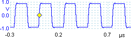
Figure 1: Square ware

Figure 2: Typical pulse train
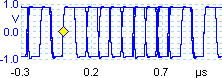
Figure 3: A number of superimposed views of the same pulse train captured with simple edge-triggering in Repeat mode
In Figure 1, the trigger point is shown by the diamond shape. The threshold is set to 0.0 V, and the scope starts to capture as soon as the signal rises above this voltage. This method gives a stable display if all the pulses are of the same shape and equally spaced.
The square wave in Figure 1 represents only one type of signal found in electronic circuits. Most signals are more complex than this, like the more realistic example in Figure 2.
In this waveform, the pulses are of unequal widths. If we use a simple edge trigger in Single trigger mode, the scope will pick the first rising edge it sees. We happened to catch the rising edge of the shortest pulse in this case, but the scope could just as easily have started capturing on any of the other rising edges. If we were looking for a narrow pulse that occurred only once in every million normal pulses, then we would be very lucky to find it using this hit-and-miss method.
In Auto or Repeat trigger mode, the scope will continue to capture many times each second. Figure 3 shows a number of waveforms superimposed, as you might see if the refresh rate is fast enough. This type of display is of little use if we want to see the data contained in the pulse train.
This brief view of edge-triggering shows that, if we want to reliably find a rare event, such as a narrow pulse buried in a string of wider pulses, then we need a more powerful type of trigger.
What Advanced Trigger Types Are Available?
Depending on what PicoScope PC Oscilloscope you use, up to 8 advanced trigger types are available:
 Advanced edge trigger

Figure 4: Rising and falling edge trigger, showing several captures superimposed
The advanced edge trigger provides the standard rising and falling edge conditions, and an additional condition called dual-edge triggering. This triggers on both edges, allowing you to check the widths and voltages of positive and negative pulses as the same time, as in Figure 4. It is useful for rapidly spotting jitter and noise problems.
The advanced trigger types also include hysteresis to reduce false triggering on noisy signals. When hysteresis is enabled, a second trigger threshold voltage is used in addition to the main threshold. The trigger fires only when the signal crosses the two thresholds in the correct order. The first threshold arms the trigger, and the second causes it to fire. An example will help to illustrate how this works.
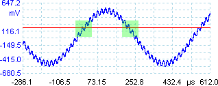
Figure 5a: Noisy signal with a single threshold
Consider the very noisy signal on the right. It is difficult to trigger reliably on this signal with a normal rising edge trigger because it crosses the trigger threshold, the red line in this example, several times in one cycle. If we zoom in on the highlighted parts of the signal, we will see how hysteresis can help.
In these zoomed-in views, the original threshold is the lower red line. The upper red line is the second threshold used by the hysteresis trigger.
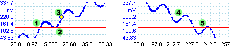
Figure 5b: Noisy signal with hysteresis threshold
The signal rises across the lower threshold at (1) and (2), arming the trigger but not firing it. At (3) the signal finally crosses the upper threshold, firing the trigger. On the falling edge of the signal, at (4) and (5), rising edges of noise pulses cause the signal to cross the upper and lower thresholds, but in the wrong order, so the trigger is not armed and does not fire. Thus the trigger occurs at only one well-defined point in the cycle, despite the noise on the signal.
 Window trigger
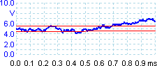
Figure 5: Window trigger
The window trigger detects the moment when the waveform enters or leaves a voltage range. This allows you to search for overvoltages and undervoltages at the same time. In Figure 5, a 5 volt power supply is monitored with thresholds of 4.5 and 5.5 volts. The window trigger would detect both the positive and negative excursions outside this range.
 Pulse width trigger
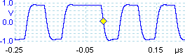
Figure 6: Pulse-width trigger
Pulse-width triggering enables you to trigger exclusively on pulses of a specified width. This can be useful for finding rare events in synchronous control signals such as write-enables, or for finding extreme values in pulse-width modulated signals.
To obtain Figure 6, the trigger was set to “pulse width, positive, greater than 70 ns”. This found a 100 ns pulse in a stream of 50 ns pulses.
 Interval trigger

Figure 7: Missing clock edges
The interval trigger helps you find missing or mistimed edges.
Figure 7 shows two examples of a 4 MHz clock waveform with a missing pulse. You could use a pulse width trigger to search for the extended high pulse in the top example or the extended low pulse in the bottom example, but the interval trigger lets you find both errors without having to change the trigger type. Setting an interval trigger of “rising, greater than 300 ns” will detect both cases. The trigger point is set to the first rising edge after the long interval.
 Window pulse width trigger

Figure 8: Windowed dwell trigger
The windowed dwell trigger is a combination of the window trigger and the pulse width trigger. It detects when the signal enters or leaves a voltage range for a specified period of time. In Figure 8, a nominally ±700 mV signal has occasional overvoltages and undervoltages, but we have set the dwell time to “greater than 100 ns” so that only abnormally wide pulses that go outside this range are detected.
 Level dropout trigger
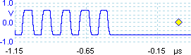
Figure 9: Level dropout trigger
The level dropout trigger detects an edge followed by a specified time with no edges. This is useful for triggering on the end of a pulse train. Figure 9 shows the end of a pulse train in which rising edges normally occur every 133 ns. The dropout trigger has detected that no rising edges have occurred within 500 ns.
 Window dropout trigger

Figure 10: Window dropout trigger
The window dropout trigger is a combination of the window trigger and the dropout trigger. It detects when the signal enters a specified voltage range and stays there for a specified time. This is useful for detecting when a signal gets stuck at a particular voltage. In Figure 10, the window dropout trigger was set to a 300 ns delay with a 600 mV to 800 mV window. It ignored the first pulse, which entered the window briefly, and the first dropout, when the signal remained below the window, but detected when the signal remained within the window for more than 300 ns.
 Logic trigger
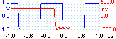
Figure 11: Logic trigger
The logic trigger can detect a number of logical combinations of the scope’s four inputs: A, B, Ext and AuxIO. The conditions that can be applied to each input vary: A and B can be level-qualified or window-qualified; Ext is level-qualified with a variable threshold; and AuxIO is level-qualified with a fixed TTL threshold. In Figure 11 the trigger was set to “Channel A, level, above 0 V, Channel B, level, below 0 V, AND”. The trigger condition became true in the middle of the trace, at time=0, when Channel A was above 0 V at the same time that Channel B was below 0 V.
Instead of the AND function, you can choose to combine the channels with other logic functions such as OR, NOR, XOR and XNOR.
How Do I Use The Advanced Trigger Types?
PicoScope 6 lets you avoid the complexity of advanced triggers unless you really need to use them. We will first look at the trigger mode control and the simple edge trigger types, before moving on to advanced triggers.
Trigger mode control
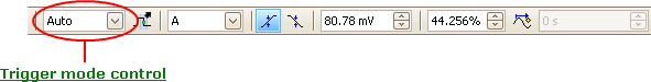
Figure 12: Location of the Trigger Mode Control
The trigger mode control, circled in Figure 12, specifies whether the scope waits for a trigger condition, and if so, how it behaves afterwards. None and ETS modes are not compatible with with advanced trigger types. If you select one of these then the advanced triggers button will not be available. Single, Repeat and Auto modes work as in any other oscilloscope. They instruct the scope to trigger on the conditions you have set, whether these are simple edge triggers or advanced triggers. You can find a full description of these trigger modes in the PicoScope 6 manual.
Standard triggering controls
The Channel, Rising edge, Falling edge and Threshold controls allow you to set up simple edge-triggering without having to open the advanced triggers dialog. Experienced scope users will find these controls familiar, even if they have not used PicoScope before, and full details can be found in the manual. The corresponding controls for advanced trigger types are found in the Advanced Triggers dialog, which we will come to soon.
Advanced Triggers button
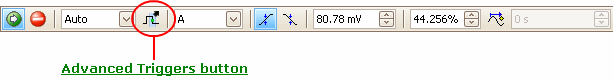
Figure 13: Location of the Advanced Triggers button
The Advanced Triggers button is the key control that lets you set up the conditions for advanced triggering.
Click this button to open the Advanced Triggers dialog. If the button is greyed out, then you are using a trigger mode that is not compatible with advanced triggering. Change the trigger mode to Auto, Repeat or Single.
Advanced Triggers dialog
This dialog appears when you click the Advanced Triggers button in the Triggering toolbar. It allows you to set up the Simple Edge trigger as well as all the advanced types.
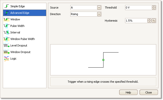
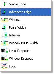
The trigger types list
Select one of trigger types in this list, and a number of options, a diagram and a description will appear on the right of the Advanced Triggers dialog.
The advanced trigger options
The options on the right-hand side of the dialog vary according to the trigger type selected from the list. In the following section we explain, in a concise format, which options apply to which trigger types. To save space, we do not describe the appearance of the dialog for every possible trigger type and combination of options.
Advanced Trigger Types
Simple Edge
Selecting this trigger type is equivalent to using the basic trigger settings on the triggering toolbar, as described earlier. You can use the Simple Edge trigger in conjunction with any trigger mode, including None and ETS.
The Source control lets you select which signal the scope should use as the trigger: set it to either A, B, Ext or AuxIO. These names correspond to the BNC input connectors on the scope device. A and B are the main measurement channels, and have variable thresholds and voltage windows. Ext is the external trigger input, which has a single variable threshold. AuxIO is the auxiliary input on the back of the scope, and has a fixed TTL threshold voltage.
The Direction control specifies the edge that will activate the trigger, and is equivalent to the rising edge and falling edge buttons on the triggering toolbar.
The Threshold control sets the voltage at which the trigger operates.
Advanced Edge
This trigger type includes the standard Rising and Falling edge triggers, but also includes the Rising or Falling edge trigger that was mentioned earlier in this article. The edge type is selected by the Direction control. The Hysteresis control sets the distance between the two trigger thresholds to improve noise rejection.
The other controls are the same as those for the Simple Edge trigger.
This and all the following trigger types are not compatible with ETS mode.
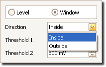
Window
This trigger type detects a signal entering or exiting a range of voltages called the ‘window’.
The Direction control specifies whether the trigger operates when the signal enters the window, exits it, or both.
The Threshold 1 and Threshold 2 controls define the upper and lower limits of the voltage window that activates the trigger. You can enter the upper and lower thresholds in either order in the two boxes, and PicoScope 6 will work out which one is the lower threshold and which one is the upper.
Pulse Width
This trigger type detects pulses within a specified range of widths.
The Pulse direction control specifies whether you want to trigger on either positive or negative pulses.
The Threshold control operates as for the Simple Edge trigger type.
The Condition control specifies whether you are looking for pulses wider or narrower than a specified width. You can also specify two pulse widths and trigger on pulses whose widths are either inside or outside those two values.
- Greater than triggers on pulses wider than the specified time.
- Less than triggers on pulses that are narrower than the specified time. This is useful for finding glitches.
The Time control specifies the pulse width for the Greater than and Less than conditions.
- Inside time range triggers on pulses that are wider than Time 1 but no wider than Time 2. This is useful for finding pulses that meet maximum and minimum width specifications.
- Outside time range does the opposite: it triggers on pulses that are either narrower than Time 1 or wider than Time 2. This is useful for finding pulses that violate a width specification.
The Time 1 and Time 2 controls specify the minimum and maximum pulse widths for the Inside time range and Outside time range trigger types.
Interval
This mode lets you search for two successive edges of the same polarity that are separated by a specified interval of time.
The Source and Threshold controls operate as for the Simple Edge trigger type.
Set the Starting edge control to either Rising or Falling according to the polarity of the edges you are interested in.
Next, set the Condition control to one of these options:
- Greater than triggers when the second edge occurs later than Time after the first edge. This is useful for detecting missing events or interruptions in a clock waveform.
- Less than triggers when the second edge occurs earlier than Time after the first edge. This is useful for detecting timing violations and spurious edges.
- Inside time range triggers when the second edge is later than Time 1 after the first edge and earlier than Time 2. This is useful for finding edges within a narrow timing range.
- Outside time range triggers when the second edge is earlier than Time 1 after the first edge or later than Time 2. This is useful for finding spurious edges that fail too meet the timing specification.
Finally, set up Time (or Time 1 and Time 2) to define the time interval or range of time intervals.
Window Pulse Width
This trigger type is a combination of the window trigger and the pulse width trigger. It detects when the signal enters a voltage window for a specified time or range of times.
The Source control operates as for the Simple Edge trigger type.
The Dwell Location control specifies whether the signal needs to Dwell Inside or Dwell Outside the window for the specified time.
The Time control or Time 1 and Time 2 controls operate as for the Pulse Width trigger type.
The Threshold 1 and Threshold 2 controls operate as for the Window trigger type.
Level Dropout
This trigger type is activated when the signal remains on one side of a threshold voltage for a specified period of time.
The Source and Threshold controls operate as for the Simple Edge trigger type.
The Dropout control specifies whether to trigger when the signal remains High, Low, or in Either state relative to the threshold.
The Time control specifies the time to wait after the last detected edge before triggering.
Window Dropout
This trigger type is a combination of the Level dropout trigger and the Window trigger. It is activated when the signal remains inside or outside a voltage window for a specified period of time.
The Source, Threshold 1 and Threshold 2 controls operate as for the Window trigger type.
The Dropout and Time controls operate as for the Level dropout trigger type.
Logic
This trigger type monitors all four scope inputs — A, B, Ext and AuxIO — at the same time, comparing each one to its own threshold or voltage window, and activates when some combination of the inputs meet their respective conditions. This trigger type does not support edge-triggering: all channels are either level-qualified or window-qualified, so the trigger does not wait for an edge but operates as soon as it sees a valid voltage.

(a) Level-qualified
(b) Window-qualified
Figure 14: Channel A or B setup for logic trigger
The Channel A and Channel B settings controls have the most options. Each one has a dialog to select either level-qualified or window-qualified operation:
With level-qualification selected, the channel is active when above or below the threshold. The Direction and Threshold controls operate as for the Simple Edge trigger type.
With window-qualification selected, the channel is active when inside or outside the specified voltage window. The Direction, Threshold 1 and Threshold 2 controls operate as for the Window trigger type.
The Ext and AuxIO settings controls have only the level-qualified options.
Each channel has a Use checkbox to the right of its settings control. Setting this box causes the channel to be included in the logic trigger, and clearing it causes the channel to be ignored.
The Logic control specifies how the four inputs are combined to produce a trigger condition. The six most common Boolean functions are provided: AND, NAND, OR, NOR, XOR and XNOR. For example: to trigger on all of the channel conditions being met, choose AND; or to trigger on none of them being met, select NOR.
Advanced triggering is available for:
- PicoScope 2205
- PicoScope 3224
- PicoScope 3424
- PicoScope 5000 Series
Note: not all trigger types are available for all models. Please check your scopes specifications to confirm which trigger types are currently available.